
Introduction
A furnace transformer has to handle rapid load changes while the furnace melts scrap or other metal, followed by long periods of heavy operation. That makes choosing the right specifications especially important.
That is why the furnace transformer specification matters more than the purchase price. A unit sized for the wrong duty can look cheaper on day one and cost more every year after.
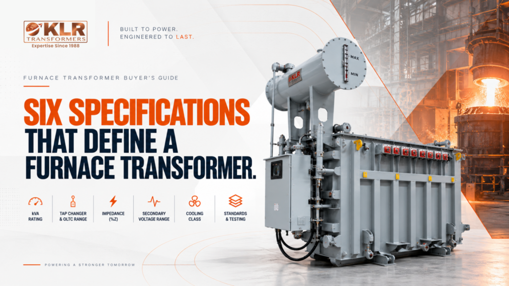
This guide covers the six parameters that define a furnace transformer, the standards to name in your Request for Quotation (RFQ), and the numbers to confirm with your furnace’s original equipment manufacturer (OEM) first. It applies to arc furnace transformer projects in India, as well as induction and ladle furnace installations.
Table of Contents:
What Is a Furnace Transformer Specification?
A furnace transformer specification sets out the ratings and design requirements the transformer needs to meet for a particular furnace. It sets the kVA rating, secondary voltage range, on-load tap changer range, impedance, cooling class and winding strength, so the unit matches the furnace’s load swings, harmonics and long hours at high load. Unlike a distribution transformer, every one of these values is chosen for the furnace, not picked from a catalogue.
Why Furnace Duty Is Different
A distribution transformer sees a steady, predictable load. An electric arc furnace does not.
- Fast load swings: current moves from open circuit to near short-circuit within a single heat.
- Harmonics: the non-linear arc produces significant 2nd, 3rd and 5th harmonic currents.
- Long hours near full load: there is little time for the unit to cool between heats.
- Mechanical stress: every current surge puts electromagnetic force on the windings.
A transformer not designed for these operating conditions may experience premature winding damage and insulation deterioration. A furnace-duty design accounts for these stresses, but its service life still depends on the actual load cycle, maintenance and operating conditions.
Six Furnace Transformer Specification Parameters
1. kVA / MVA Rating
The transformer rating should account for the furnace’s maximum demand and duty cycle, not just its nameplate rating. A simple way to reach a starting figure:
- Take the furnace’s rated power in kW from the nameplate or OEM data.
- Divide it by the power factor to get kVA. For example, a furnace drawing 800 kW at a power factor of 0.8 needs 1,000 kVA (800 ÷ 0.8).
- Add a margin for harmonics, ambient temperature, altitude, duty cycle and planned production growth.
- Round up to the next standard rating, never down.
Check the result against your actual load data, not only the nameplate. Treat this as a starting point, and confirm the final capacity and thermal margin with your furnace OEM before finalising the specification.
2. Tap Changer and On-Load Tap Changer (OLTC) Range
The OLTC range and switching duty are especially important for an arc furnace. During the melt, operators adjust the secondary voltage, usually using a higher voltage during bore-in and a lower voltage during refining. Confirm the full voltage curve and expected switching frequency with your furnace manufacturer. Other furnace types may manage with an off-circuit tap changer, depending on how much voltage adjustment the process needs. Confirm this with your OEM.
For arc furnace duty, specify:
- A tap range wide enough to cover the OEM’s full voltage curve, commonly ±10% or more
- Fine steps, typically 17–33 tap positions, depending on the required voltage range and furnace operating conditions
- A heavy-duty OLTC rated for frequent switching, since a furnace OLTC can operate tens of thousands of times a year, against a few thousand for a grid transformer
- An in-tank or external OLTC, based on your space and maintenance needs
3. Impedance Voltage (%Z)
Impedance controls how much current flows when an electrode touches the melt or another electrode. Furnace transformers use a higher %Z on purpose.
- Electric arc furnaces: 6–10%
- Induction furnaces: 5–8%
- Ladle furnaces: 6–9%
The impedance required for a furnace transformer differs from that of a typical distribution unit. The final value should be selected with the furnace OEM, considering the required current and system design. Some furnace designs also use a series reactor.
4. Secondary Voltage Range
The required secondary voltage range depends on the furnace design and electrode configuration. Furnaces draw high current at a comparatively low voltage, so this range is worth getting right. Confirm the minimum and maximum values with your furnace OEM before placing the order.
The range is usually shaped by:
- The furnace type and design: arc, submerged arc, induction or ladle
- The electrode or coil configuration
- The operating stages, since melting and refining often need different voltages
- The power and current the furnace needs at each stage
Ask your OEM for the voltage and current figures for each operating stage in writing, so the manufacturer works from the same numbers you do.
5. Cooling Class and Thermal Design
Furnace transformers can operate at high loads for long periods, so the cooling arrangement needs to suit the transformer’s rating and operating conditions. The right option depends on factors such as loading pattern, ambient temperature and installation conditions; confirm the requirement with the manufacturer.
Tell the manufacturer early whether the unit will be indoors or outdoors, and share the ambient temperature, installation altitude, ventilation and available space.
If the transformer will be installed in a coastal or corrosive environment, discuss suitable corrosion protection for the tank and radiators with the manufacturer.
6. Winding Design and Short-Circuit Withstand
Furnace operation can subject transformer windings to significant mechanical forces. When reviewing a supplier’s proposal, check the following:
- The conductor material and winding type
- Mechanical reinforcement against repeated short-circuit forces
- Short-circuit withstand to IEC 60076-5, shown by calculation or type test evidence
- A delta-connected secondary winding, which is common in furnace duty and helps circulate triplen harmonic currents inside the winding
When reviewing a furnace transformer proposal, ask the manufacturer to specify the winding material, winding arrangement, insulation system and short-circuit withstand provisions for the proposed unit. These details should be confirmed against the approved technical documentation.
Arc Furnace vs Induction Furnace Transformer
Although both types need careful specification, their operating conditions affect which design parameters need the most attention.
An arc furnace sets the hardest demands: severe load swings, a wide OLTC range and higher impedance. An induction furnace transformer sees a steadier load, so its impedance is usually lower. Converter-fed induction furnaces produce their own harmonics, so winding phase shift and harmonic limits deserve attention.
Standards to Name in Your RFQ
When preparing an RFQ in India, specify the applicable parts of IS 2026 and include any additional standards required for your project. These may include:
- IEC 60214-1: on-load tap changer performance and tests
- IEC 60076-5: short-circuit withstand capability
- IEEE 519: harmonic distortion limits at the supply connection
If your project involves a PSU or an EPC contractor, check the tender documents early to see whether specific type-test reports or accreditation requirements apply.
Every furnace transformer undergoes routine testing by KLR in accordance with applicable IS and IEC requirements. Type tests can also be arranged on request. KLR’s in-house laboratory, equipped with an impulse testing facility, supports the testing process. If your tender requires a specific test report or certificate, our team can provide the documentation on request.
Three Numbers to Confirm Before You Issue the RFQ
Ask your furnace OEM for:
- Maximum secondary voltage
- Minimum secondary voltage
- Maximum furnace rated current
Get these three values from your furnace OEM before issuing the RFQ. They help the manufacturer determine the required voltage range and conductor sizing.
How KLR Transformers Builds Furnace Transformers
KLR Transformers manufactures furnace transformers at its Pashamylaram facility in Hyderabad for steel, metal, foundry and ferro-alloy applications. Each unit is customised to the buyer’s furnace requirements, with customers served across India and international markets.
- Furnace types covered: induction, arc, ladle and ferro-alloy furnaces.
- Built around your furnace data: each unit is designed from the electrical and process details your furnace OEM provides.
- Support after delivery: annual maintenance contracts (AMC), on-site servicing and testing.
Conclusion
Before issuing your RFQ, confirm the transformer rating, voltage range, tap changer, impedance, cooling and winding requirements with your furnace OEM. Include the applicable standards and testing requirements in the specification.
Planning a steel, foundry or ferro-alloy project? We’d be glad to help.
Share your furnace type (induction or arc), MVA rating, secondary voltage and duty cycle. Our engineering team will review your requirements and share a technical proposal within one business day, Contact Us.
Email: marketing@klrtransformers.com | Phone: +91 96420 04300
FAQ Section
Arc furnace transformers usually have an impedance of 6–10%, which is higher than a typical distribution unit. The higher value limits fault current when electrodes touch the melt or each other. Some designs add a series reactor, so confirm the exact value with your furnace OEM.
Operators adjust the secondary voltage during the melt, typically using higher voltage at bore-in and lower voltage during refining. An on-load tap changer (OLTC) makes these changes without de-energising the furnace. Confirm the full voltage curve and expected switching frequency with your furnace OEM.
Start with the furnace’s rated power in kW and divide it by the power factor to get kVA. Add a margin for harmonics, temperature, altitude, duty cycle and planned growth, then round up to the next standard rating. Your furnace OEM should confirm the final capacity and thermal margin.
Indian buyers should specify the applicable parts of IS 2026 and add any standards the project needs. Common additions are IEC 60214-1 for on-load tap changers, IEC 60076-5 for short-circuit withstand, and IEEE 519 for harmonic limits. For PSU or EPC tenders, check early for type-test report or accreditation requirements.
Induction furnace loads are steadier than arc furnace loads, so impedance is usually lower, at 5–8% compared with 6–10% for arc furnaces. Converter-fed induction furnaces produce their own harmonics, so winding phase shift and harmonic limits need attention. Arc furnaces place the heaviest demand on the tap changer.
The right cooling arrangement depends on the transformer’s rating, loading pattern, ambient temperature and installation conditions, since furnace transformers can run at high loads for long periods. Share these details with the manufacturer early, and discuss corrosion protection for the tank and radiators if the site is coastal or corrosive.
Share the furnace type (induction or arc), MVA rating, secondary voltage, maximum furnace current and duty cycle. With these, a manufacturer can size the tap changer, conductors and cooling. KLR Transformers’ engineering team responds within one business day with a technical proposal.